How It Works: Electronics Cooling Package
On a Commercial Electric Vehicle, the inverter, converter, OBC (On board charger) and traction motor will self-heat during operation. To improve performance, durability and safety, it is important to manage the temperature of these critical assets known as the power electronics. In general, heavy-duty vehicles demand and consume more power driven by far higher torque during operation than the average light duty vehicle or car requiring a deeper consideration of thermal management for the power electronics. All of these power electronic components can have varied derating temperature requirements ranging from 50 – 65 oC. If the power electronic component temperatures creep above their recommended derating temperature, it could result in a significant reduction in output power capability. Additionally, if the component temperature is allowed to rise above the operating range, it can result in a failure making the vehicle in-operable.
For example, for the inverter, the power output will rely on the derating temperature of the inverter’s power module, and it also runs the risk of overheating and shutting down if the temperature rises above the operating range recommended by the manufacturer.

Commercial EVs typically have a cooling package for the inverter, converter, OBC (On Board Charger) and traction motor. Each one of these power electronics will have an integrated cooling architecture through which a coolant is flown through to allow heat transfer from the internal components to the coolant. This coolant is then routed through the cooling package to reject the heat to ambient before circulating back through the power electronics.
Each one – inverter, converter, OBC (On Board Charger) traction motor – has a different derating temperature requirement. The cooling package should be sized for the worst case combined heat rejection requirement while maintaining a coolant out temperature to be below the lowest derating temperature among the power electronic components in the loop. Positioning of each of the Power electronic components in the Coolant loop is an equally critical consideration when designing the power electronics coolant loop.
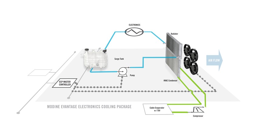
The schematic on the left shows a typical electronics cooling package (ECP) design which has a radiator to reject heat from the coolant to ambient air, and an array of fans to increase air flow through the radiator to maximize heat transfer. The speed of the fans will be modulated depending on the cooling needed to minimize power draw. In addition to the ECP, coolant pumps and a surge tank may be added to the coolant loop to help manage flow of the coolant to and from the vehicle’s power electronics and the ECP.
An ECP is designed to be a complete, plug-and-play system with an integrated master controller to intelligently control operation of the fan array and coolant pumps. An Electronics Cooling Package provides a complete system, including all necessary heat exchangers, fan array, wiring harness as well as a master controller with tailored firmware to provide complete operation upon delivery, enabling fast and easy integration into the vehicle’s chassis.